|
nesgate
VHDL emulation of the Nintendo Entertainment System
|

|
|
nesgate
VHDL emulation of the Nintendo Entertainment System
|
|
Entities | |
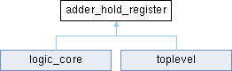
| adder_hold_register.rtl | architecture |
Ports | ||
| load | std_ulogic | |
| data_in | std_ulogic_vector ( 7 downto 0 ) | |
| The data to be loaded into the register. | ||
| sb_bus_enable_ADD_SB_0_6 | in | std_ulogic |
ADD/SB(0-6) - Enable Adder Hold Register SB Bus Outpu, bits 0-6 | ||
| sb_bus_enable_ADD_SB_7 | in | std_ulogic |
ADD/SB(7) - Enable Adder Hold Register SB Bus Outpu, bit 7 | ||
| sb_bus_port | out | std_ulogic_vector ( 7 downto 0 ) |
| Port for the SB bus of the MOS 6502. | ||
| adl_bus_enable_ADD_ADL | in | std_ulogic |
ADD/ADL - Enable Adder Hold Register ADL Bus Output | ||
| adl_bus_port | out | std_ulogic_vector ( 7 downto 0 ) |
| Port for the ADL bus of the MOS 6502. | ||
|
Port |
|
Port |
Port for the ADL bus of the MOS 6502.
|
Port |
The data to be loaded into the register.
|
Port |
Load signal for the register from the data input Should be wired to the clock generator Phi2 output
|
Port |
|
Port |
|
Port |
Port for the SB bus of the MOS 6502.